Api Oil Water Separator Design Manual
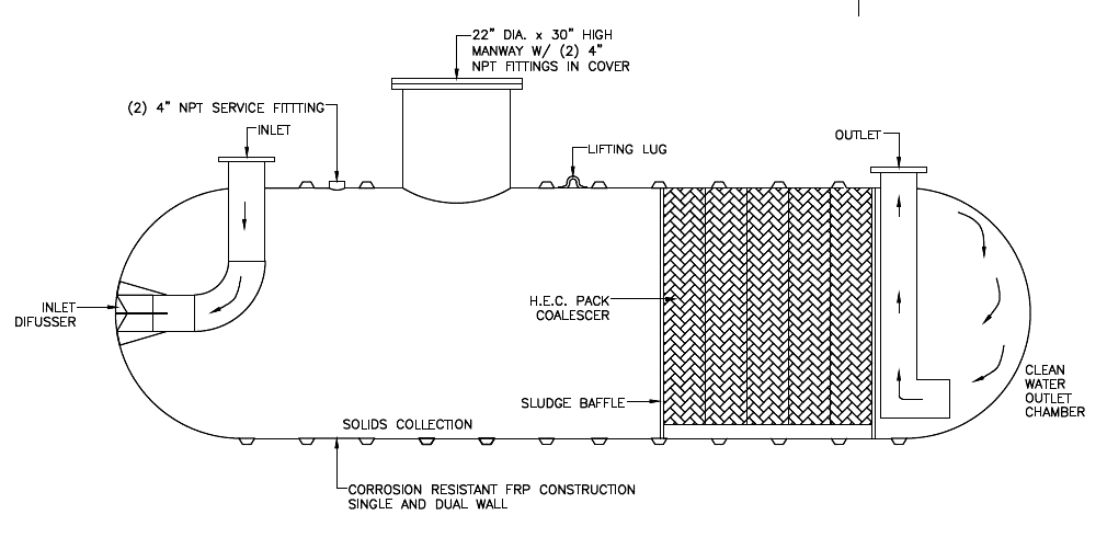
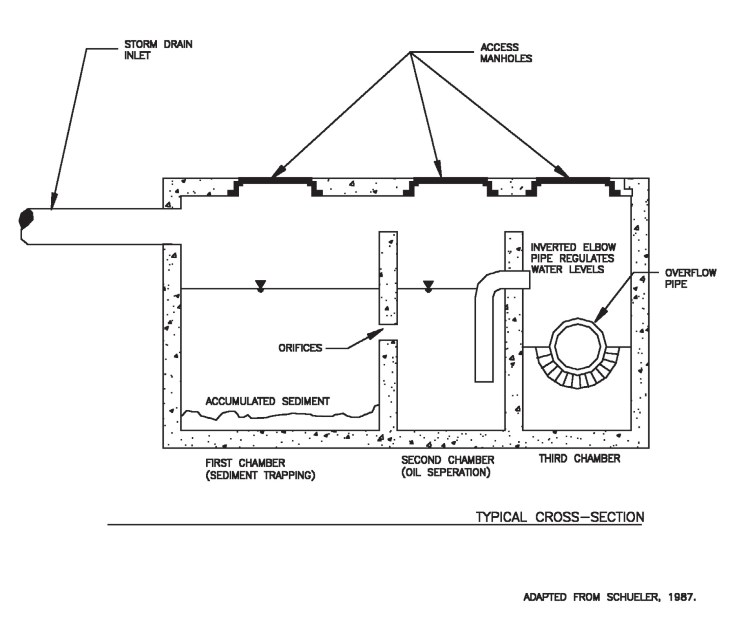
Two baffles separate the influent chamber.
Api oil water separator design manual. However spacings down to 25 inches have been used successfully. 142 oil and gas separation design and sizing. Liquid capacity 6. The flow capacities of the design are based on an influent of fresh water and no.
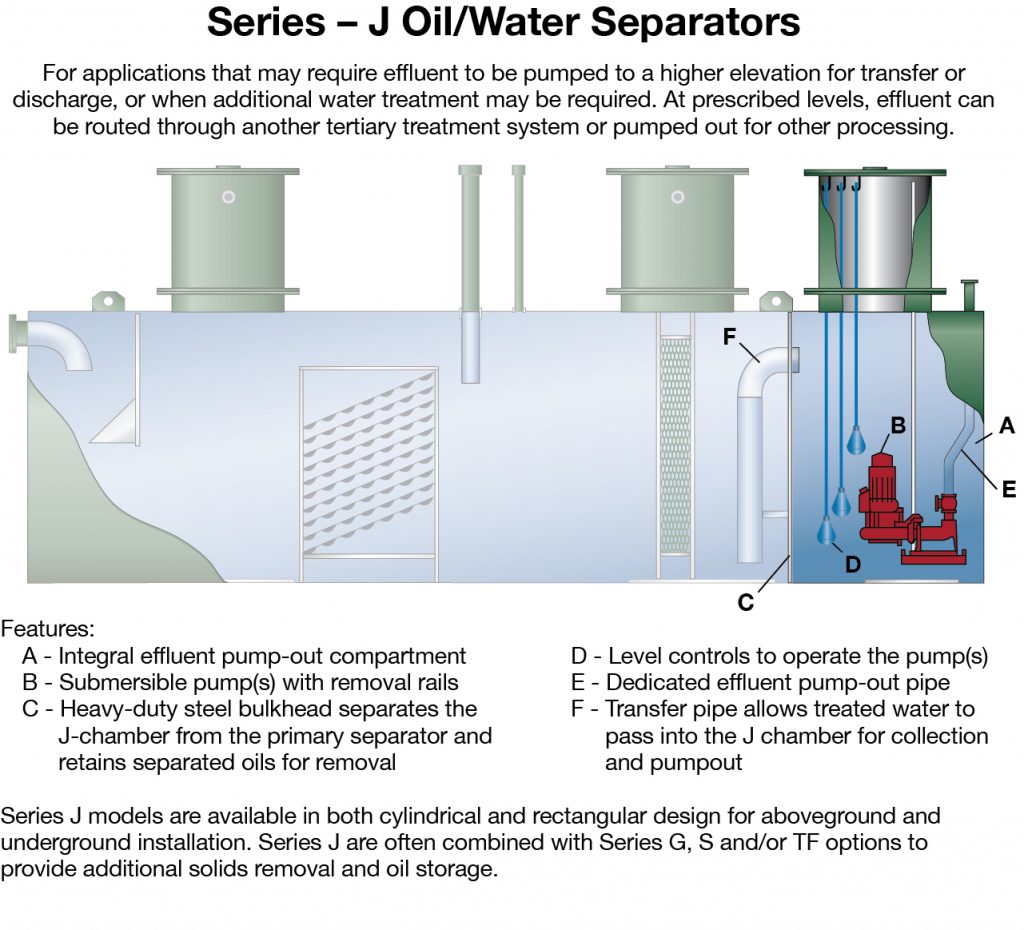
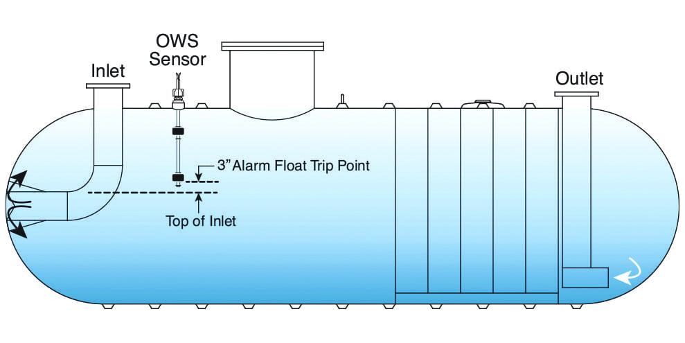
Api separators are gravity type separators and are usually equipped with oil removal facilities. An influent chamber the main separator chamber and an effluent chamber. Api tanks were originally designed by the american petroleum institute api for use in refinery applications but modifications of the design can be used for stormwater treatment. Table of contents.
Separator types 2 3 factors affecting separation 3 4. Internal construction of separators 1 2. Below is a link to an api oil water separator sizing spreadsheet developed by hydro flo technologies. The spreadsheet operates on microsoft excel 2003 or later.
The separator itself has three chambers separated by baffles. Oil and gas separation design manual. 33 1 2 types of separator api tanks see figure 33 1 and plate separators are the more efficient oil separators. Below is a sample shot of the spreadsheet.
Api 1990 stated that conventional oil water separators are designed based on the design criteria summarized as follows. I horizontal velocity of wastewater through the oil water separator should be less than or equal to 0 9144 metre minute 3 feet per minute or 15 times the rise rate v t of the oil globules 15 v t whichever is smallerii. According to api design recommendations api publication 421 design and operation of oil water separators the typical range of spacing between the plates is 75 to 1 5 inches. The api separator is a gravity separation device designed using stokes law principles that define the rise velocity of oil droplets based on their density size and water properties the design of the separator is based on the specific gravity difference between the oil and the wastewater because that difference is much smaller than the specific gravity difference between the suspended solids.
Conventional separators api a typical conventional separator system is shown in figure 1. Example problems 8 9. A design method is provided in the api manual on disposal of refinery wastes chapters 5 and 6oil water separator process design and construction details api publication 1630 1979. By inputting the major design criteria you can solve for the separation chambers width to length to depth ratios.
The influent chamber removes free oil that has already separated from the oil water mixture during conveyance to the unit. Chapter 5 oil water separators 5 1 introduction the intended use of an oil water separator s ows determines whether the separator is subject to the spcc regulations and if so what provisions are applicable. Gas capacity 4 5. The direction of water flow is generally crossflow or downflow through the coalescing packs.
Api oil water separators the api separator design is based on the american petroleum institute api monographs on refinery environmental control design and operation of oil water separators.








-2_copy-resized-600.jpg)


